DVI Erweiterung der 3dfx Voodoo 5 5500 PCI
Don’t worry, translation in (my) English is following below.
In einem gemeinsamen Projekt und der nötigen Eigendynamik haben wir, mehrere Member aus dem Voodooalert Forum, eine nachbausichere Möglichkeit ersonnen um die 3dfx Voodoo 5 5500 PCI mit einem DVI Ausgang zu versehen.
Also look here: Voodooalert DVI Project Link
Die PCI Version der 3dfx Voodoo 5 5500 PCI Karte hat den DVI Bereich unbestückt. Um sie mit DVI auszurüsten sind fünf Arbeitsschritte notwendig.
- RTFM zu erst
- Bauteile entfernen
- Bauteile bestücken
- Bios Flash
- Slotbracket bearbeiten
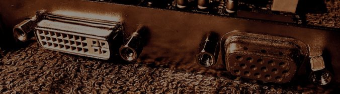
Auf dem Bild seht Ihr meine eigene Voodoo 5 5500 PCI mit dem von mir hinzugefügten DVI Ausgang.
Manual (Read it or you’ll fuck up the project)
PDF: V5-DVI-Upgrade-Rv2.1
Es folgen Baustufenfotos von mir zugeschickten Grafikkarten, sowie die dazu gehörenden Beschreibungen. Ab hier geht es nun in Englisch weiter.
Now English will be used.
Step 1 – Prepare your Graphics Card
Dismount bracket by removing the Philips Screw as well as the two hexagonal bolts using 3/16″ nut driver. Keep it aside.

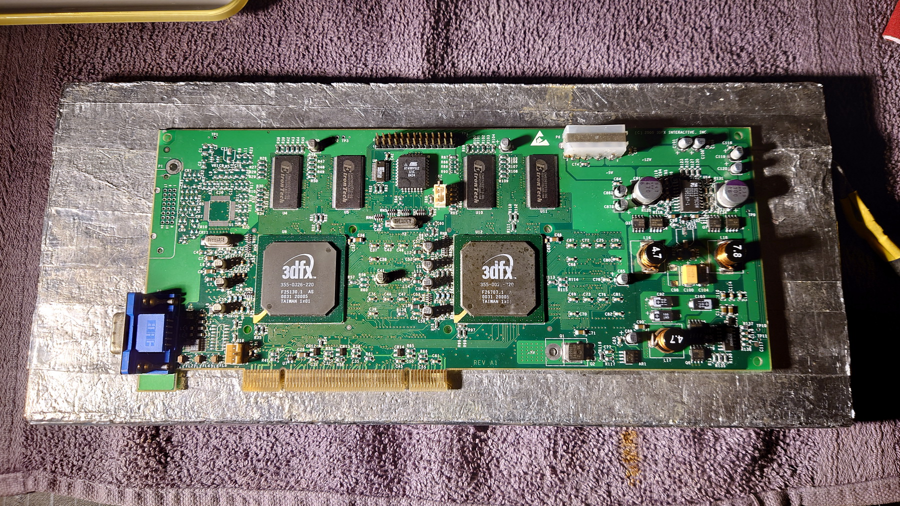
Now put the graphics card on a preheater. This one is homebrew. It is strongly advised to preheat the board to about 60°C/140°F before working on it.
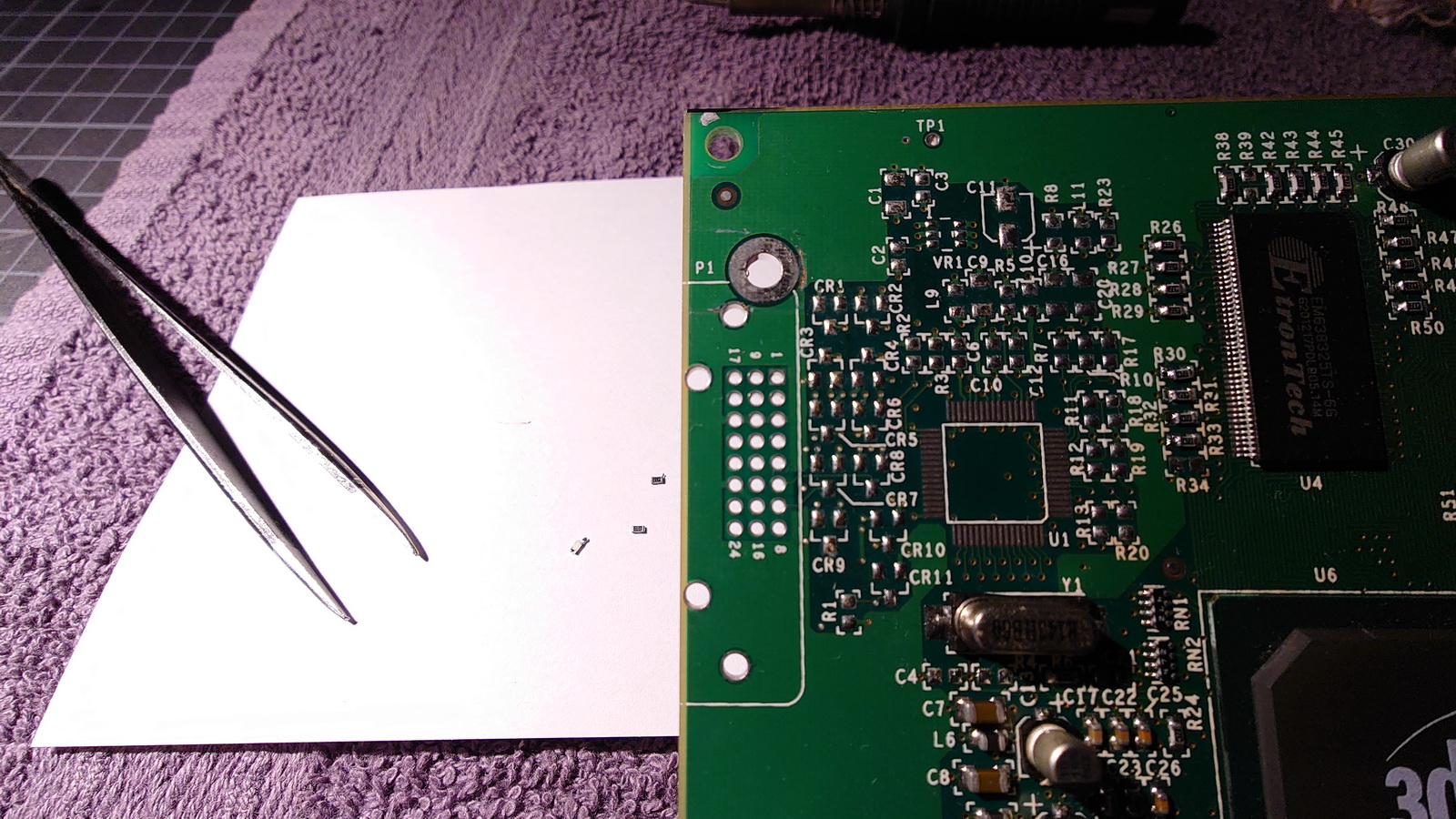
Step 2 – Remove the components that are not needed
Please refer to the manual
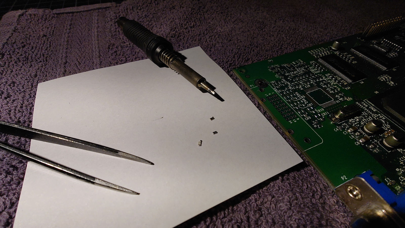
Please remove tin from all retaining holes and vias.
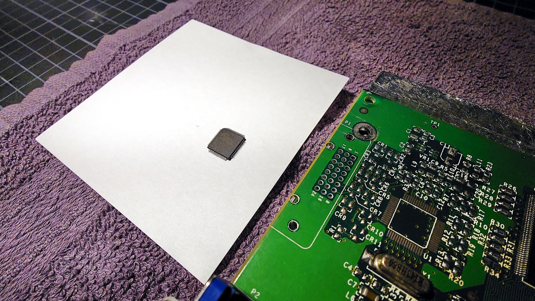
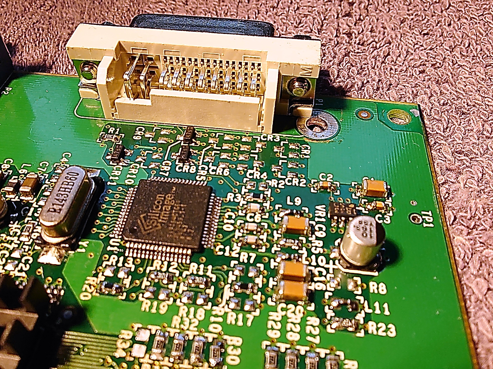
Step 3 – Placement of the components on the PCB
The biggest challenge is the application of the silicon image chip [U1]. It is extremely important to prepare the solder pads properly and then clean them very thoroughly.
Heat the whole PCB using the preheater device.The chip must be positioned very precisely and then only test-fit it with a few pins to check that all pads are in touch with all pins aligned. High quality tin and flux is very important for the success of a clean and beautiful soldering. Keep the soldering time as short as possible. Touch each pin briefly.
DVI Connector has been insalled and all components on front side.
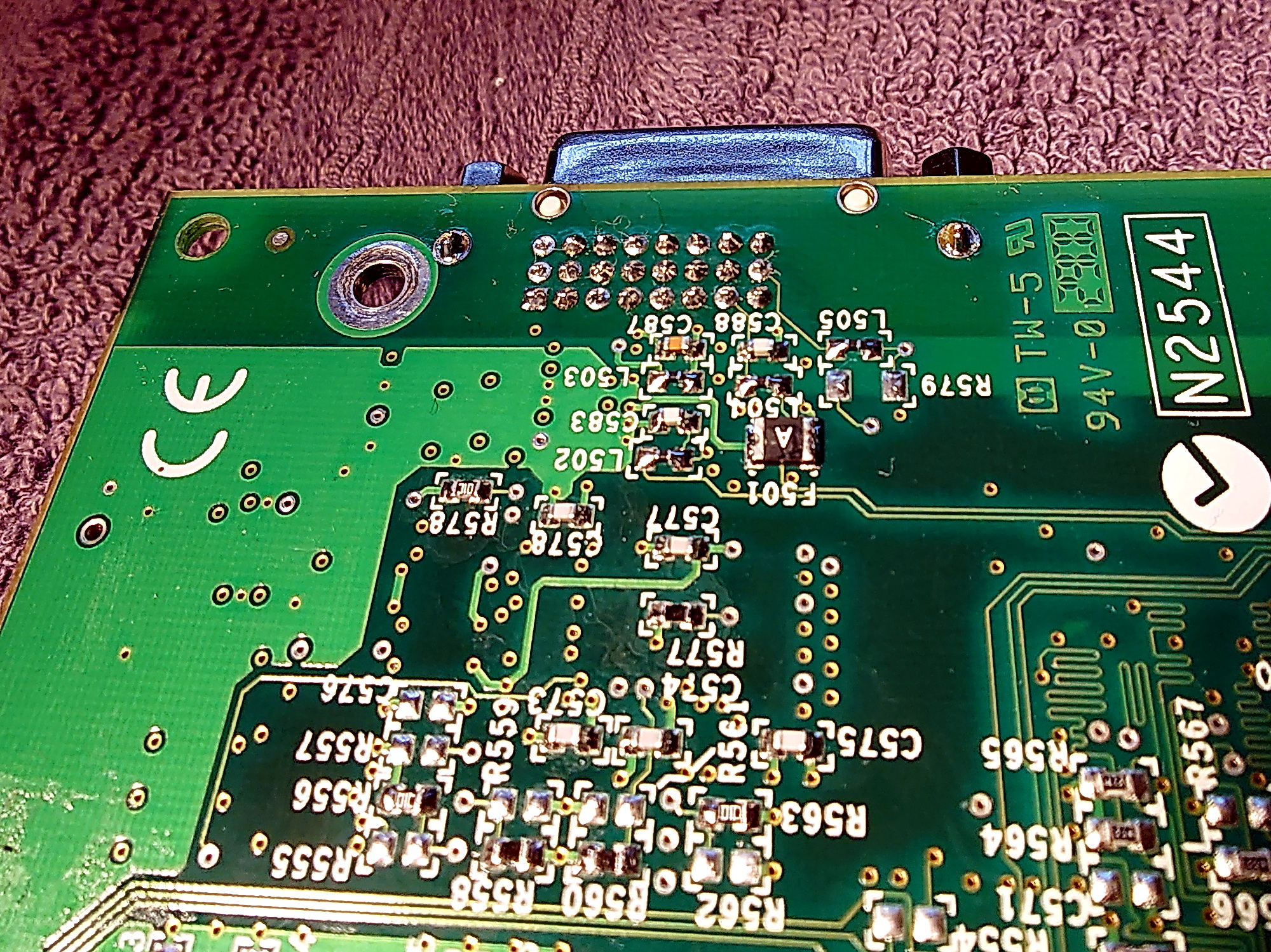
Backside, carefully solder the vias für the connector pins. Proper heat is important. The fuse as well as the residual parts are in place.
Please clean the PCB carefully and do a test of the card. When the card works like before it’s time to go on to activate the DVI Part. Proceed to the next step.
Step 4 – Activation of DVI capability
To activate the DVI functions the BIOS of the card has to be a version that supports the DVI capabilitys. Basically it is up to you which DVI supporting BIOS version you want to install. Therefore, you can find everything you need here.
![]() Or easily take this version.
Or easily take this version.
[Click on the picture to the left for download]
This version has proven itself in several Voodoo 5 5500 PCI to DVI upgrades. After you have flashed the BIOS go making some tests. The System where you installed the card before this conversion, the OS will detect a new hardware and ask for the path to the driver. Install the same driver like before. The 3dfx tools should detect a digital output automatically. If you did all right and the 3dfx tools detect the digital output, you finally can connect a monitor with DVI input. Restart your system. Your Voodoo 5 should detect dhere is a DVI device connected and gives a nice picture.If not – well, you may did some wrong oder there is an other problem what has to be troubleshooted.
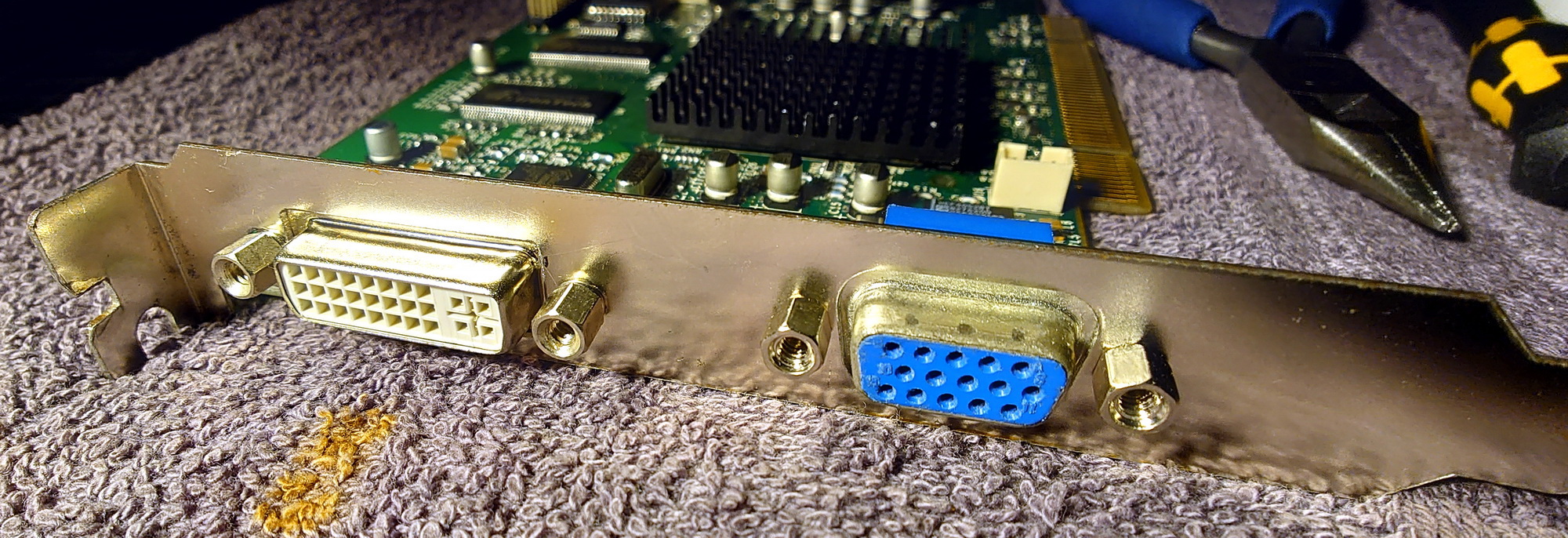
Step 5 – The Slot Bracket
You can easily make the cut-out for the DVI connector yourself.
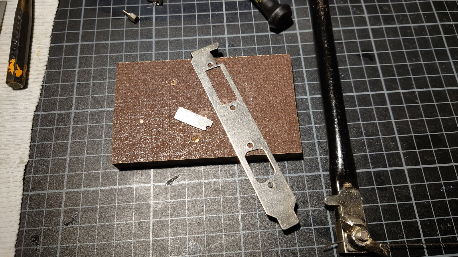
Here you can see that it doesn’t take very much. A coping saw with metal saw blade, a centre punch, 3.2mm (1/8″) drill, 100g hammer and some key files. Simply transfer the dimensions and positions to the old slot bracket and process it with the tools.
Well done, great job. You did it! 🙂
You’ve made a Voodoo 5 5500 PCI DVI. A Voodoo Card that is now similar to a Voodoo 5 PCI MAC.
! Alongside with this project, new and very neat slotbrackets has been developed and are in production. Hence there will be single and dual brackets available. The Dual Brackets have double width, like this engineering sample made from plastics. Here you can already see the engravings that will later be found on the engravings made of high-quality aluminium and lined with paint.
See you soon…
– Backfire –